计算机图形学
阅读数:150 评论数:0
跳转到新版页面分类
图形/语音
正文
1、变换与坐标系
<投影矩阵>*<视图矩阵>*<模型矩阵>*<顶点坐标>
相乘的顺序不能改变。物体本身拥有一个坐标系,叫本地坐标系。把物体放到世界坐标系中,采用了模型矩阵,就是执行缩放、平移、旋转操作的过程。此时物体就具有了世界坐标系。 再加入上帝之眼,就是视图矩阵,包括视点坐标,观察点坐标,和上方向。现在只差最后一步–投影矩阵,物体就可以呈现出来了。 目前显示设备都是二维平面的,所以需要投影矩阵来转换物体。投影矩阵通常分为平行投影和透视投影。
2、模型矩阵
将点的初始位置的坐标P映射到平移、旋转、缩放后的位置坐标P’,即:
$\left[ \begin{aligned} &x\\&y\\&z \end{aligned} \right] \longrightarrow \left[ \begin{aligned} &\acute{x}\\&\acute{y}\\&\acute{z} \end{aligned} \right]$
(1)平移变换
$ \left[ \begin{aligned} &\acute{x}\\&\acute{y}\\&\acute{z} \end{aligned} \right] = \left[ \begin{aligned} &x\\&y\\&z \end{aligned} \right] +\left[ \begin{aligned} &t_x\\&t_y\\&t_z \end{aligned} \right]$
(2)旋转变化
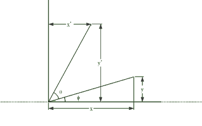
设置线段长度为L
$x = L\cos(\phi)$
$y = L\sin(\phi)$
$\acute{x} = L\cos(\phi+\theta)$
$\Rightarrow L\cos(\phi)\cos(\theta)-L\sin(\phi)\sin(\theta)$
$\Rightarrow x\cos(\theta)-y\sin(\theta)$
$\acute{y} = L\sin(\phi+\theta)$
$\Rightarrow L\sin(\phi)\cos(\theta)+L\cos(\phi)\sin(\theta)$
$\Rightarrow y\cos(\theta)+xsin(\theta)$
使用矩阵表达
$\left[ \begin{aligned} &\acute{x}\\&\acute{y} \end{aligned}\right] = \left[ \begin{aligned} &\cos(\theta) &-\sin(\theta)\\&\sin(\theta) &\cos(\theta) \end{aligned} \right] \left[ \begin{aligned} &x\\&y\end{aligned}\right]$
推广到三维空间中
点绕z轴旋转:
$\left[ \begin{aligned} &\acute{x}\\&\acute{y}\\&\acute{z} \end{aligned}\right] = \left[ \begin{array}{3} \cos(\theta) &-\sin(\theta) &0\\ \sin(\theta) &\cos(\theta) &0\\ 0 &0 &1 \end{array} \right] \left[ \begin{aligned} &x\\&y\\&z \end{aligned}\right]$
点绕x轴旋转
$\left[ \begin{aligned} &\acute{x}\\&\acute{y}\\&\acute{z} \end{aligned}\right] = \left[ \begin{array}{3} 1 &0 &0 \\ 0 &\cos(\theta) &-\sin(\theta) \\ 0 &\sin(\theta) &\cos(\theta) \end{array} \right] \left[ \begin{aligned} &x\\&y\\&z \end{aligned}\right]$
点绕y轴旋转
$\left[ \begin{aligned} &\acute{x}\\&\acute{y}\\&\acute{z} \end{aligned}\right] = \left[ \begin{array}{3} \cos(\theta) &0 &-\sin(\theta) \\ 0 &1 &0 \\ \sin(\theta) &0 &\cos(\theta) \end{array} \right] \left[ \begin{aligned} &x\\&y\\&z \end{aligned}\right]$
(3)缩放变化
$\left[ \begin{aligned} &\acute{x}\\&\acute{y}\\&\acute{z} \end{aligned}\right] = \left[ \begin{array}{3} s_x &0 &0\\ 0 &s_y &0 \\ 0 &0 &s_z \end{array} \right] \left[ \begin{aligned} &x\\&y\\&z \end{aligned}\right]$
平移变换,变换后点坐标等于初始位置点坐标加上一个平移向量;而旋转变换和缩放变换,变换后点坐标等于初始位置点坐标乘以一个变换矩阵。
$\acute{P} = P+T, \acute{P}=R\cdot P, \acute{P}=S\cdot P$
使用齐次坐标后,平移变化也可以表示成初始位置坐标左乘一个变换矩阵的形式,它使用4个分量来表示三维空间中的点,前三个分量和普通坐标一样,第四个分量为1。
$\left[ \begin{aligned} &x\\&y\\&z \end{aligned} \right] \longrightarrow \left[ \begin{aligned} &\acute{x}\\&\acute{y}\\&\acute{z}\\&1 \end{aligned} \right]$
矩阵有一个性质:
$M\cdot (A\cdot B) = (M\cdotA)\cdot B$
模型矩阵之所以称之为“模型矩阵”,是因为该矩阵与点的位置没有关系,仅仅包含了一系列变换的信息。而在三维世界中,一个模型里所有的顶点往往共享同一个变换,对应同一个模型矩阵。
齐次坐标还有一个优点,能够区分点和向量:在普通坐标里,点和向量都是由三个分量组成的,表示位置的点坐标(2,3,4)和表示方向的向量(2,3,4)没有区别。而在齐次坐标中,第四个分量可以区分它们,点坐标的第四个分量为1,而向量坐标第四个分量为0。
3、视图矩阵
在模型矩阵中,我们关心的是空间中的点在经历变换后在世界坐标系下的位置。事实上,我们更加关心空间中的点相对于观察者的位置。最简单的方案是将观察者置于原点处,面向z轴(或x轴、y轴)正半轴,那么空间中的点在世界坐标系下的位置就是其相对于观察者的位置。
视图矩阵同样也可以分为平移、旋转和缩放,视图矩阵是将观察者视为一个模型,获得的观察者在世界中变换的模型矩阵的逆矩阵。
4、投影矩阵
投影矩阵则将这些顶点坐标映射到二维的屏幕上,即:
$\left[ \begin{aligned} &x\\&y\\&z\\&1 \end{aligned} \right] \longrightarrow \left[ \begin{aligned} &\acute{x}\\&\acute{y} \end{aligned} \right]$
最主要的有两种投影方式,正射投影和透视投影。前者用于精确制图,如工业零件侧视图或建筑物顶视图,从屏幕上就可以量测平行于屏幕的线段长度;后者用于模拟视觉,远处的物体看上去较小。
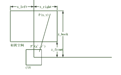
三维世界的显示中,屏幕模拟了一个窗口,你透过这个窗口观察“外面”的世界。你的屏幕是有边缘的(除非你有一个球形的房间,内壁全是屏幕),因此你仅仅能观察到那个世界的一部分,即“相机空间”。相机空间的左、右、上、下边界是受限于屏幕的边缘,同时也设定前、后边界,因为你很难看清太近或太远的东西。在正射投影中,相机空间是一个规则的立方体,而在透视投影中则是一个方台体。
(1)正射投影
定义一个规范的视窗区域(CCV),为x,y,z都处在区间[-1,1]之间的边长为2的立方体。x和y坐标值用来线形拉伸到到实际屏幕上,而z值存储了“深度”。而投影的过程就是将三维空间中的点从相机空间映射到CCV中。
正射投影非常简单,直接将矩形的相机空间线形压缩到CCV中即可。采取顶视图,相机空间的左右边界为 $x_{left}$ 和 $x_{right}$ :
$\dfrac{x-x_{left}}{x_{right}-x_{left}} = \dfrac{\acute{x}-(-1)}{1-(-1)}$
$\Rightarrow \acute{x} = \dfrac{2}{x_{right}-x_{left}}\cdot x - \dfrac{x_{right}+x_{left}}{x_{right}-x{left}}$
推广到y轴和z轴:
$\left[ \begin{aligned} \acute{x}\\ \acute{y} \\ \acute{z} \\ 1 \end{aligned}\right] = \left[ \begin{array}{4} \dfrac{2}{x_{right}-x_{left}} &0 &0 &-\dfrac{x_{right}+x_{left}}{x_{right}-x_{left}}\\ 0 &\dfrac{2}{y_{top}-x_{bottom}} &0 &-\dfrac{y_{top}+y_{bottom}}{y_{top}-y_{bottom}}\\ 0 &0 &\dfrac{2}{z_{back}-z_{front}} &-\dfrac{z_{back}+z_{front}}{z_{back}-z_{front}} \\ 0 &0 &0 &1 \end{array} \right] \cdot \left[ \begin{aligned} x\\ y \\ z \\ 1 \end{aligned}\right]$
(2)透视投影
透视投影相对较为复杂
$\left[ \begin{aligned} z\cdot \acute{x}\\ z\cdot \acute{y} \\ z\cdot \acute{z} \\ z \end{aligned}\right] = \left[ \begin{array}{4} \dfrac{2}{x_{right}-x_{left}} &0 &-\dfrac{x_{right}+x_{left}}{x_{right}-x_{left}} &0 \\ 0 &\dfrac{2}{y_{top}-y_{bottom}} &-\dfrac{y_{top}+y_{bottom}}{y_{top}-y_{bottom}} &0 \\ 0 &0 &t_z &s_z \\ 0 &0 &1 &0 \end{array} \right] \cdot \left[ \begin{aligned} x\\ y \\ z \\ 1 \end{aligned} \right]$
透视投影矩阵尾行是(0,0,1,0),这样就将计算得到的坐标的第四个分量赋值为z而不是1。将相机空间左乘投影矩阵后的结果不是一个CCV空间,如果你将这个空间画出来,会发现其仍然是一个方台形。这时进行“透视除法”,将上一步得到的点坐标化为第四个分量为1的标准齐次坐标:
$\left[ \begin{aligned} &\acute{x}\\&\acute{y}\\&\acute{z}\\ &1 \end{aligned} \right] = \left[ \begin{aligned} z\cdot \acute{x}\\z\cdot \acute{y}\\z\cdot \acute{z}\\ \acute{z} \end{aligned} \right] \cdot \dfrac{1}{z}$
然后我们直接取齐次坐标中的x’和y’值,并将其线形映射到屏幕上,比如点(0,0)出现在屏幕中央,点(-1,1)出现在屏幕左上角。


